In this post, we will explore the basics of computer graphics by implementing a simple raytracer in Python. We will also use the raytracer as an example to experiment with Python type checking to catch more bugs and create self-documenting code. The implementation of the raytracer follows the fantastic book “Computer Graphics from Scartch” from Gabriel Gambetta.
Let’s start from the very beginning:
What is a raytracer?
A raytracer is computer graphics technique to create realistic images by simulating how a rays of light hit different 3d objects. More advanced raytracers also simulate how the light is scattered and bounced around depending on the specific surface that it hits, but we are going to focus on a very simple raytracer in this post.
The basic idea is very simple. Imagine you want to draw a picture somewhere outside of say a beautiful house, but unfortunately, you are not really very good at drawing. One trick that you could use would be the following:
Take a metal grid with a very fine mesh, say 1x1cm and put it in front of the object you want to paint. Now for each metal grid section, check which color you see. Paint this color on the corresponding place on your paper. Checkout the image below (imagine that my drawing skills are better and the rays intersect nicely with the grid)
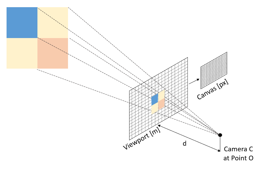
The individual steps are:
1. Imagine you place a camera C at some point O
2. Now let’s assume you have a metal grid d meters in front of you called the viewport
3. For every grid section of the viewport, you check the color that you see and you color the corresponding part on your paper canvas with that color (so we rescale the object)
The finer the grid you use, the more accurate the picture you are going to get on your paper canvas. If you switch the paper canvas for a computer screen, we color pixels instead of paper.
Raytracer Implementation
Based on the logic we described in the previous section, we get the following pseudo code implementation:
for each pixel on our screen canvas:
    check which viewport grid corresponds to it
    draw a straight line from your camera through the viewport grid
    if line hits an object:
        if object is closest object:
            return object color
    else:
        return background color

    pixel color = returned color
To implement this in Python, we will go step-by-step:
- We define a canvas to draw on and position our camera.
- Then we add objects to the canvas (spheres in our case).
- Next, we add lights to our canvas to simulate shadows.
- Finally, we render the scene.
Let’s get started from the beginning and import the libraries we are going to use:
from typing import List, Protocol, Tuple, NamedTuple
import numpy as np
from matplotlib import pyplot as plot
Next, we are going to define a type alias and a few helper classes:
rgb = Tuple[int, int, int]

class Point3d(NamedTuple):
    x: float
    y: float
    z: float

class Object(Protocol):
    _color: rgb

    def intersect_ray_object(self, O: Point3d, D: Point3d) -> Tuple[float, float]:
        """
        A method that takes the camera position O with [x,y,z] and the position on the viewport D with [x,y,z]  and returns the rgb color
        """
        ...
    def get_normal_vec(self, O: Point3d, D: Point3d, closest_t: float) -> Tuple[np.ndarray, np.ndarray]:
        """
        A method that takes the camera position O with [x,y,z], the position on the viewport D with [x,y,z] and the closest_t from ray line and returns the Normal Vector N and the point P as a tuple
        """
        ...
I use the type-alias rgb above to provide a descriptive name for our type hints so you can read e.g. a function signature and immediately know that yes, the function accepts a tuple of integers, but those integers correspond to rgb color channels. Initially, I was toying with the idea to define rgb as Tuple[0<=int<=255,0<=int<=255,0<=int<=255]. The typing library that ships with Python does not support to define sub-types of integer and I haven’t found a nice looking solution yet, so I decided to stick with int and follow Gabriel’s implementation to clamp the ints if necessary to [0, 255].
Then I define an Object Protocol. Protocols in Python allow you to specify interfaces. In this case, we specify that every class that implements the Object protocol has to have a color defined by a variable called _rgb and has to implement two methods, intersect_ray_object() and get_normal_vec(). So if you want to have a cube in our scene, all you need to do is implement the interface described above.
Let’s start by implementing a sphere:
class Sphere(Object):
    def __init__(self, center: Point3d, radius: float, color: rgb) -> None:
        self._center = center
        self._radius = radius
        self._color = color

    def intersect_ray_object(self, O: Point3d, D: Point3d) -> Tuple[float, float]:
        CO = np.subtract(O, self._center)
        a = np.dot(D, D)
        b = 2*np.dot(CO, D)
        c = np.dot(CO, CO) - self._radius**2

        discrimiant = b**2 - 4*a*c
        if discrimiant < 0:
            return (np.inf, np.inf)

        t1 = (-b + np.sqrt(discrimiant))/(2*a)
        t2 = (-b - np.sqrt(discrimiant))/(2*a)

        return (t1, t2)

    def get_normal_vec(self, O: Point3d, D: Point3d, closest_t: float) -> Tuple[np.ndarray, np.ndarray]:
        P = np.add(O, closest_t * np.array(D))
        N = P - np.array(self._center)
        N = N / len(N)

        return (N, P)
As you can see, the Sphere has a variable called _color that is of type rgb and implements the two methods described before. The implementation of intersect_ray_object is very simple in this case (which is why we are using spheres in the first place:). We need two equations to calculate the intersection between our ray and the sphere:
- Ray equation: $P = O + t(V - O)$, where point $P$ is on the line drawn between our camera at origin $O$ an the corresponding viewport point $V$ that we shoot the ray through. We will call $(V - O)=D$ for direction.
- Sphere equation: $
= r^2$, where $<>$ is the dot-product, $C$ is the center of the sphere and $P$ is a point on the surface.
The ray intersects the sphere if and only if the ray and the sphere equation are both satisfied at the same time. So let’s subsitute $P$ from our ray equation into our sphere equation:
$$
So all we need to do is solve the quadratic equation we know and love from high-school :) $$ (t_1, t_2) = \frac{-b \pm(b^2 - 4ac)}{2a} $$ Geometrically speaking, we have three possibilities:
- Ray does NOT intersect the sphere: we have no solution to the above equation
- Ray is a tangent to sphere: we have exactly one solution
- Ray passes through the front of the sphere and exits at the back: we have two solutions
Since we only want to render spheres that are in-front of the camera, we will only consider $t>0$ and if there are multiple solutions, we will take the smallest $t$, aka when the ray hits the sphere in the front and not when it exits at the back.
We need the normal vector later to implement shadows and you can look up the formula on Wikipedia for more details if you are interested.
Now we can go forward and define our Canvas class. The Canvas will be responsible for storing our scene (aka the objects and lights we define) and then rendering the scene.
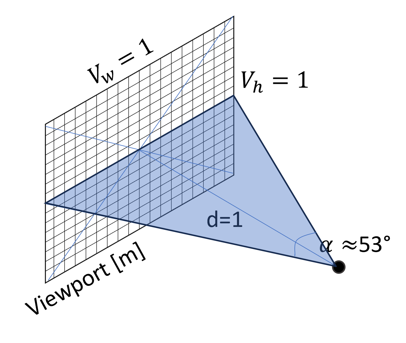
We will give set our viewport to have viewport width $V_w=1$ and viewport height $V_h=1$ and we will set the distance $d$ between our camera and the viewport to $d=1$ as well. Note that the viewport is defined in realworld units (e.g. meters). Using more high-school math you can calculate that we get a field of view $\alpha$ of roughly 53°:
All that is left is to convert from our canvas (measured in pixels) to the real-world viewport (measured e.g. in meters). So if we set our canvas height $C_h = 640px$ and our canvas width $C_w= 640px$, we get that for every pixel on the canvas, we move $1⁄640$, aka $V_w/C_W$ in the viewport. That means that we get:
$$ V_x = C_x \frac{V_w}{C_w} = C_x \frac{1}{640} \newline V_y = C_y \frac{V_h}{C_h} =C_y \frac{1}{640} \newline V_z = d =1 $$
That means we are now ready to implement our Canvas class:
class Canvas(object):
    def __init__(self, Cw: int, Ch: int) -> None:
        self._Cw = Cw # x = columns
        self._Ch = Ch # y = rows
        self._vw = 1 # viewport width in real world units (e.g. meter)
        self._vh = 1 # viewport height in real world units (e.g. meter)
        self._d = 1 # viewport distance from camera
        self._background_color = (255, 255, 255)

        # Create a numpy array containing a vector (0, 0, 0) at each (x, y) position for the rgb channels
        self.img = np.zeros((Ch, Cw, 3), dtype=np.int32)

    def put_pixel(self, x: int, y: int, color: Tuple[float, float, float]) -> None:
        """
        Put pixel relative to center of canvas
        """
        s_x = int(self._Cw / 2) + x
        s_y = int(self._Ch / 2) + y

        self.img[s_y, s_x] = self.clamp_color(color)

    def clamp_color(self, color: Tuple[float, float, float]) -> rgb:
        """
        Makes sure that colors are within rgb 0 - 255 and integers
        """

        clamped_color = tuple(int(max(min(255, channel), 0)) for channel in color)

        return clamped_color

    def canvas_to_viewport(self, x: int, y: int) -> Point3d:
        """
        Take pixel as input and output corresponding real world coordinates
        """

        return Point3d(x*self._vw/self._Cw, y * self._vh/self._Ch, self._d)

    def add_objects(self, objects: List[Object]) -> None:
        """
        Add objects to the scene that get drawn on the canvas
        """
        self._objects = objects

    def add_lights(self, lights) -> None:
        """
        Add lights to the scene that cause shadows on the canvas
        """
        self._lights = lights

    def trace_ray(self, O: Point3d, D: Point3d, t_min: float, t_max: float) -> rgb:
        """
        For each pixel on the canvas, calculate corresponding viewport and check which objects the ray intersects when passing through the view port.
        Use the color to paint the pixel
        """
        closest_t = np.inf
        closest_object = None

        for object in self._objects:
            t1, t2 = object.intersect_ray_object(O, D)
            if t_min < t1 and t1 < t_max and t1 < closest_t:
                closest_t = t1
                closest_object = object
            if t_min < t2 and t2 < t_max and t2 < closest_t:
                closest_t = t2
                closest_object = object

        if closest_object is None:
            return self._background_color
        else:
            N, P = closest_object.get_normal_vec(O, D, closest_t)
            rgb_float = np.multiply(closest_object._color, self.compute_lighting(P, N))

            object_color = self.clamp_color(tuple(rgb_float))

            return object_color

    def compute_lighting(self, P: np.ndarray, N: np.ndarray) -> float:
        i = 0

        for light in self._lights:
            if light["type"] == "ambient":
                i += light["intensity"]
            else:
                if light["type"] == "point":
                    L = np.subtract(light["position"], P)
                else:
                    L = light["direction"]

                n_dot_l = np.dot(N, L)
                if n_dot_l > 0:
                    i += light["intensity"] * n_dot_l/(len(N) + len(L))

        return i

    def render(self, O: Point3d) -> None:
        fig = plot.figure()
        ax = fig.add_subplot(1,1,1)
        ax.set_aspect('equal', 'box')

        for x in range(int(-self._Cw/2), int(self._Cw/2)):
            for y in range(int(-self._Ch/2), int(self._Ch/2)):
                D = self.canvas_to_viewport(x, y)
                color = self.trace_ray(O, D, 1, np.inf)
                self.put_pixel(x, y, color)

        ax.imshow(self.img.astype(np.uint8))
As you can see above, we set the viewport to 1x1 and a white background color. The put_pixel() method is just a convenience to move the origin to the middle of the canvas instead of the top-left. The method clamp_color() ensures that we only get valid rgb colors. The method canvas_to_viewport() implements the conversion from pixel coordinates to viewport coordinates as discussed before. The two methods add_objects() and add_lights() store the scene and trace_ray() simply calls the intersect_ray_object() method for each object and returns the color of the closest one and the background color if there is no intersection. The method compute_lightning() simply applies an adjustment to the color brightness depending on the angle the ray intersects with the object.
Finally, render() simply iterates over each pixel and creates the final image.
Let’s check the output:
Cw = 640
Ch = 640
O = Point3d(0.0, 0.0, 0.0)

sphere1 = Sphere(Point3d(2, 2, 3), 2, (255, 100, 0))
sphere2 = Sphere(Point3d(0, 0, 4), 1, (0, 0, 255))
sphere3 = Sphere(Point3d(-2, 0.5, 4), 1, (0, 255, 0))
sphere4 = Sphere(Point3d(0, 5001,0), 5000, (255, 255, 0))


# Intensities sum up to 1
light1 = {"type": "ambient", "intensity": 0.2}
light2 = {"type": "point", "intensity": 0.6, "position": [0.5,0.5,0]}
light3 = {"type": "directional", "intensity": 0.2, "direction": [1,4,4]}

canvas = Canvas(Cw, Ch)
canvas.add_objects([sphere1, sphere2, sphere3, sphere4])
canvas.add_lights([light1, light2, light3])
canvas.render(O)
The code above gives us the following image:
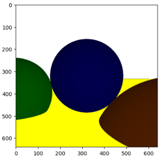
That’s it. We implemented a simple raytracer while leveraging Python type hints and protocols to make the code easier to understand and to extend.
Addendum: I just realized that this post has been sitting basically finished just without explanatory graphics for almost exactly one year (Dezember 25th, 2022), but finally it is done :)